BrewPiLess
Use an ESP8266 to replace RPI and Arduino. Running BrewPi without Pi, therefore, BrewPi-Less
#Pressure monitor and Auto Spunding The feature is not yet verified.
By using a pressure transducer, BPL can read pressure and control the pressure if Auto Spunding(capping) is enabled.
Hardware Setup
Transducer
The pressure transducers supported are something like this: Pressure Transducer. Using other types might be possible, but the output should be linear voltage.
ADC
On-board ADC, A0 of ESP8266, 36 of ESP32, and external ADS1115 can be used to read from the transducer.
ESP8266 bulit-in ADC, A0
The reading of A0, on-board ADC, is not stable when WiFi is activated, because ESP8266 uses the ADC for WiFi related tasks. Therefore, it is highly recommended to use external ADS1115 when controlling is required.
ADC of ESP8266 reads voltage from 0-1.0V, and there are resistors on D1 mini, and NodeMcu, to make ADC input range 0-3.3v. A resistor might be needed to extend the range 0-5v.
ESP32
Only ADC1 is allowed. Pin 36 is choosen by default. ADC of ESP32 isn’t linear, and calibration is necessary. The calibration recommended by the the chip vendor has been adapted. However, the result might not be satisfiying.
ADS1115
Connect I2C of ADS1115, and A0 to the transducer. Connect ADDR, address selection pin, to GND, so that the address is 0x48. I2C LCDs of address 0x48 are unusable unless disabling ADS1115 support.
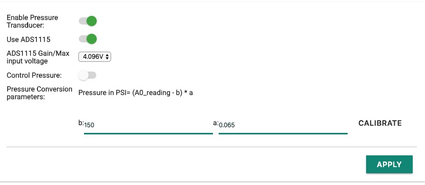
ADS1115 Gain/Max input voltage should be set according to the real value of the transducer. The bigger the maximum voltage, the lower the resolution.
| Max Voltage | resolution |
|---|---|
| 6.144 V | 187.5 uV = 0.000187 V |
| 4.096 V | 125 uV = 0.000125 V |
| 2.048 V | 62.5 uV = 0.0000625 V |
| 1.024 V | 31.25 uV = 0.00003125 V |
| 0.512 V | 15.625 uV = 0.000015625 V |
| 0.256 V | 7.8125 uV = 0.0000078125 V |
Conversion
BPL converts ADC readings from pressure transducer into pressure.
The formula used is
PSI=(A0_Reading - b) * a
Take the pressure transducer that I have for example, output: 0.5 - 4.5v linear maximum pressure: 80psi (4.5v)
The output:
| pressure | voltage | A0 reading |
|---|---|---|
| 0 | 0.5v | 1023 * 0.5/3.3= 155 |
| 40 | 2.5v | 1023 * 2.5/3.3= 775 |
| 80 | 4.5v | 1023 (saturated) |
Given the fact that I don’t really care the reading that exceeds 40psi. I just save a resistor and connect the output direct to A0. My formula is
PSI=(A0_Reading - 155) * (40-0)/(775-155) => PSI=(A0_Reading - 155) * 0.06452
example 2: ADS1115 In my case, Max input voltage is set to 4.096V, in which one step increase of ADC value is 0.000125V. So
| pressure | voltage | ADC reading |
|---|---|---|
| 0 | 0.5v | 0.5/0.000125= 4,000 |
| 40 | 2.5v | 2.5/0.000125= 20,000 |
The formula would be
PSI=(ADC_Reading - 4,000) * (40-0)/(20,000-4,000) => (ADC_Reading - 4,000) * 0.0025
Getting parameters by real readings
In practice, there are errors, and the readings sometimes are not exact the same as expected. A simple way to get the formula is using “calibration” function by
- Step 1: make sure there is “NO pressure”. And click the button to get “b”.
- Step 2: put the transducer under a pressure closer maximum the better. Input the pressure and click “Step 2” button.
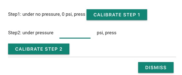
BPL will then derive the parameters automatically.
Pressure Control
“Capping control” is necessary to support pressure control. A solenoid is needed to vent the gas/co2 when necessary. The most tricky part is the venting. A small pin hole or gap should work. **Venting flow should be close to the speed of CO2 generation.
** BPL checks the pressure every second, if the pressure is greater than specified value, the solenoid will be open. The less the gas/pressure is released in 1 second, the more precise the pressure control is. It might sound like difficult. The fact is that it is more difficult to make something air tight. A threaded pipe and cap without seal might do the job.